Since the Raspberry Pi Pico was on sale approximately six months ago, I believe it has been used in a variety of electrical crafts and peripheral modules. In these conditions, I experimented with employing a pyroelectric motion sensor that was described in the official manual to detect motion. The switch science online shop sells the sensor that was utilised this time.

We will utilise the user-friendly programming language MicroPython for this project. Burn the firmware that MicroPython uses to run on the Raspberry Pi Pico that can be downloaded from this page using the "Download UF2 file" link. To store the downloaded UF2 file with D&D after burning, press the "BOOT SEL" button on the main unit and attach it to the PC so that it will be recognised as a folder.

Install Thonny as well, as it provides a practical setting for running MicroPython experiments. To switch to Raspberry Pi Pico, click the location where Python is written below. It will first be run in Python.

The pyroelectric sensor employed is the HC-SR501, which is also mentioned on page 81 of the official manual. As instructed, connect VO, GP28, GND to GND, and VCC to VBUS.

import machine as m
import utime

sensor = m.Pin(28, m.Pin.IN, m.Pin.PULL_DOWN) //センサの接続ポート
led = m.Pin(25, m.Pin.OUT) // 本体のLEDを使用する.

while True:
     led.value(sensor.value()) //取得した状態をそのままLEDに流す
Turn the variable resistor on the main unit using this code to change the sensitivity and time. The left side of the variable resistor is the sensitivity, and the right side is the time, as viewed from the front. Time moves in a clockwise direction, and sensitivity is constant. Set a reasonable figure since if you turn the time adjustment all the way up, it will be High for a very long time (if nothing happens, the default value is fine).

Thonny's "execute" button will only turn on when motion is detected, as you can see in the image above.

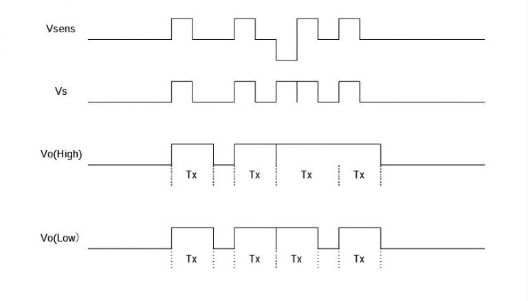
The movement of the BIS0001 element, which is the element employed in this sensor, is seen in the image below. (I believe the default setting is Low.)
Here, rewrite the code. Since it is now spinning endlessly, extra operations may cause the movement to become unstable. So let's use a trigger interrupt to make it work.
import machine as m
import utime

sensor = m.Pin(28, m.Pin.IN, m.Pin.PULL_DOWN)
led = m.Pin(25, m.Pin.OUT)

def sensor_callback(Pin):
  //させたい処理を書く
    led.value(1)
    utime.sleep_ms(250)
    led.value(0)

sensor.irq(trigger = m.Pin.IRQ_RISING, handler = sensor_callback)
Now that the sensor has responded, we have a function that will be invoked. After that, simply include the processing in the function that you want to run when motion is detected, and it will function.
Arduino development for the Raspberry Pi Pico
We have described how to utilise the PIR sensor up to this point. From this point on, we'll get ready and explain how to make Pico into an Arduino. Install the Arduino IDE as we'll be utilising it.
To start, use the Arduino IDE's "Tools" > "Board" > "Board Manager" search to look for "Pico."
further set up the initial "Arduino Mbed OS RP2040 Boards."
Once that is done, choose "Tools" > "Boards" > "Arduino MbedOS RP2040 Boards" > "Raspberry Pi Pico."
The set of tasks is finished with this. Try Hello World, shall we?
void setup() {
  // put your setup code here, to run once:
  Serial.begin(9600);
}

void loop() {
  // put your main code here, to run repeatedly:
  Serial.println("hello world");
}
Press the "BOOT SEL" button on the main unit while creating a programme and establishing a connection to the PC.
Press the arrow button at the top of the screen to create and write, much as with an Arduino Uno. After writing, choose the Raspberry Pi Pico port under "Tools" > "Serial Port" to view the serial monitor.
What do you say? Has it displayed correctly?
Following that, you can train to become an Arduino
Create a PIR motion sensor using the Raspberry Pi Pico and Arduino.
I simply wanted to type this baffling phrase.
Let's first determine the sensor's condition.
void setup(){
     pinMode(25, OUTPUT);
     pinMode(28, INPUT_PULLDOWN);
     Serial.begin(9600);
}

void loop(){
     int value = digitalRead(28);
     Serial.println(value)
     digitalWrite(25, value);
}
and use the serial monitor and the main unit's LED to examine the sensor's status.
Let's now configure interrupts in a manner similar to that used while building MicroPython. "attachInterrupt()" is the interrupt function. The description of that function is given below.
///
/// pin = 割り込みを設定するピン番号
/// func = 呼び出すコールバック関数
/// mode = RISING, FALLING, CHANGE, LOWそれぞれ
///       立上がり,立下り,両方, LOW状態に反応する
attachInterrupt(int pin, void(*)() func, int mode);
void setup() {
Serial.begin(9600); //シリアル通信を有効化
pinMode(28, INPUT_PULLDOWN); //28番(PIRセンサ出力)を入力に設定
attachInterrupt(28, Sensor_Callback, CHANGE);
//割り込みを28番にしてエッジ認識設定
pinMode(25, OUTPUT); //25番(本体LED)を出力に設定
}
void Sensor_Callback(){
digitalWrite(25, digitalRead(28)); //センサ出力をLEDで表示する
}
void loop() {
}This completes the code that causes the main unit's LED to illuminate as the sensor responds.
Summary
I began by attempting to handle the PIR sensor in accordance with the published manual. Due to Pico's nature, I believe that it is now finally feasible to develop Pico with an Arduino. Whether you are using raspberry pi oder Arduino, both platforms offer flexibility and innovation in projects.Why not attempt Pico Arduino development?
Source: Switch Science Magazine


.png)