LoRaWAN is a long-range, low-power protocol with a low bandwidth. With a good antenna, you might get 15 kilometres of range from an off-the-shelf LoRa radio, which is intended to link battery-powered remote sensors to the internet through a gateway. In the negative side, usable bandwidth would be calculated in bytes rather than megabytes or even kilobytes.

Sandeep Mistry, the author of the Arduino LoRa library, who also recently added Ethernet support for Pico, put together support for LoRa compatibility for Pico. Using the Semtech SX1276 radio module, his library adds LoRa support to Pico and other RP2040-based boards. As a result, breakout boards such as Adafruit's RFM95W and LoRa FeatherWing are completely supported.
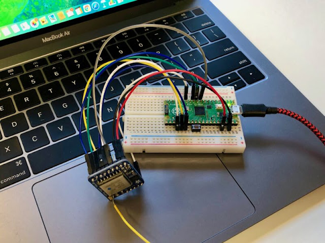 |
| Image Credit Raspberrypi.org |
Is there any LoRaWAN coverage?
You'll need to be within range of a LoRa gateway to use a LoraWAN-enabled Pico. The Things Network, an open-source community LoRaWAN network with worldwide reach, comes to the rescue.
It's likely that you're already covered, depending on where you're based. If you aren't, though, you shouldn't be too concerned.

The days when a LoRaWAN base station will set you back several thousand dollars are long gone. A LoRa portal is now available for around £75. However, a few years ago, created my own portal. Perhaps unsurprisingly, it was built around a Raspberry Pi.
Obtaining a source
Make sure your pico-sdk checkout, including submodules, is up to date if you already have the Raspberry Pi Pico toolchain installed and running. If not, you'll need to first instal the C/C++ SDK before downloading the project from GitHub.
$ git clone --recurse-submodules https://github.com/sandeepmistry/pico-lorawan.git $ cd pico_lorawan
Before continuing, double-check that your PICO_SDK_PATH is fixed. If you're using a Raspberry Pi and have run the pico_setup.sh script or followed the directions in Pico Getting Started guide, for example, you'd set the PICO_SDK_PATH to
$ export PICO_SDK_PATH = /home/pi/pico/pico-sdk
After that, both the library and the sample programmes are ready to be developed. But first, we'll need to setup the cloud infrastructure where our data will be stored, as well as link our LoRa radio board to our Raspberry Pi Pico.
Create a programme.
Although every LoRa system in range of the new gateway will have its packets collected and sent upstream to The Things Network, data packets will be dumped on the ground because they have a destination. In other words, The Things Network must know where to redirect the packets received by the gateway.
To provide it with this knowledge, we must first construct an application inside The Things Network Console. To do this, simply enter a specific Application ID string — whatever will do — and the console will create an Application EUI and a default Access Key, which we will use to register our devices to our application.

If we've registered an application, what we have to do is register our particular device — or, in the future, a group of devices — to that application so that the backend knows where to route packets from that device.
Device Registration
The application's page in the console can be used to register our computer.

Our remote device is identified by the Device ID, which is a human-readable string. Since the Adafruit RFM9W breakout board comes with a sticker in the same bag as the radio with a special identifier written on it, we can use it to postpend a string to uniquely mark our Pico board, so we end up with something like pico-xy-xy-xy-xy-xy-xy
In addition, we'll need to create a Device EUI2. This is a 64-bit one-of-a-kind identifier. To produce our Device EUI, we can once again use the unique identifier from the sticker, except this time we can simply pad it with two leading zeros, 0000XYXYXYXYXYXY To create the Device EUI, you may also use pico_get_unique_board_id( ).
If you look at your Device page after registration, you'll see that you'll need the Application EUI2 and Application Key2 to allow your board to communicate with the LoRa network, or more specifically, to allow the network to correctly route packets from your board to your application.
2 Write down your Device EUI, Application EUI, and Application Key.
Putting items together on a breadboard
After we've configured our cloud backend, the next step is to bind our Pico to the LoRa breakout board. Unfortunately, the RFM95W breakout is not designed to be used on a breadboard. At the very least, it's not breadboard-friendly if you need access to the radio's pins on both sides of the board, like we do with this project — the breakout is just a tad too big for a normal breadboard in this situation.

Fortunately, it is not a major issue, but you would most likely need to obtain a number of male-to-female jumper wires in addition to your breadboard. Connect the RFM95W module to your Raspberry Pi Pico now. The pin mapping between the breakout board's pins and your Pico should be as follows:
| Pico | RP20401 | SX1276 Module | RFM95W Breakout |
| 3V3 (OUT) | — | VCC | VIN |
| GND | GND | GND | GND |
| Pin 10 | GP7 | DIO0 | G0 |
| Pin 11 | GP8 | NSS | CS |
| Pin 12 | GP9 | RESET | RST |
| Pin 14 | GP10 | DIO1 | G1 |
| Pin 21 | GP16 (SPI0 RX) | MISO | MISO |
| Pin 24 | GP18 (SPI0 SCK) | SCK | SCK |
| Pin 25 | GP19 (SPI0 TX) | MOSI | MOSI |
1 This are the library's default pins, which can be modified in apps.
Computer development and deployment
Now that we've set up our backend in the cloud and physically "made" our antenna, we can develop and deploy our LoRaWAN programme. One of the library's example applications can read the temperature from the on-chip sensor on the RP2040 microcontroller and transmit it to the Things Network application on a regular basis via the LoRaWAN radio.
void internal_temperature_init() {
    adc_init();
    adc_select_input(4);
    adc_set_temp_sensor_enabled(true);
}

float internal_temperature_get() {
    float adc_voltage = adc_read() * 3.3f / 4096;
    float adc_temperature = 27 - (adc_voltage - 0.706f) / 0.001721f;

    return adc_temperature;
}
Shift the directory in your checkout to the otaa_temperature_led sample programme. Since this example employs OTAA, we'll need the Device EUI, Application EUI, and Application Key that we created.
otaa_temperature_led
Adjust the Area, REGION, DEVICE_EUI, APP_EUI values in the config.h file to the values displayed in the Network Console. Instead of the byte array representation, the code expects the (default) string format, with no spaces between the hexadecimal digits.
#define LORAWAN_REGION LORAMAC_REGION_EU868 #define LORAWAN_DEVICE_EUI "Insert your Device EUI" #define LORAWAN_APP_EUI "Insert your Application EUI" #define LORAWAN_APP_KEY "Insert your App Key" #define LORAWAN_CHANNEL_MASK NULL
I'm in the United Kingdom, and my LoRa radio broadcasts at 868MHz, so I'll set my region to LORAMAC_REGION_EU868. If you live in the United States, you must set your country to LORAMAC_REGION_US915.
After you've modified the config.h file, you may proceed to construct the sample applications.
$ cd ../.. $ mkdir build $ cd build $ cmake .. $ make
If all goes well, you should have a UF2 file named pico_lorawan_otaa_temperature_led.uf2 in build/examples/otaa_temperature_led/. You can now load this UF2 file into your Pico as normal.
Take your Raspberry Pi Pico board and a micro USB cable with you. Connect the cable to your Raspberry Pi or laptop, and then press and hold the BOOTSEL button on your Pico while inserting the other end of the micro USB cable into the board. Then, once the board is plugged in, release the switch.
RPI-RP2 can appear as a disc volume on your desktop. To open it, double-click it and then drag and drop the UF2 file into it. If you are experiencing difficulties, please see Chapter 4 of our Getting Started guide for more details.
Your Pico is now running your LoRaWAN programme, and if you open a USB Serial link to it, you should be able to see some debugging stuff. Start minicom in a Terminal pane.
$ minicom -D /dev/ttyACM0Data Transmission
To see the true information, however, you must go to the Network console. An initial join message should be shown, followed by a series of frames. Each frame represents a temperature measurement sent from your Pico to The Things Network application through LoRaWAN and the Gateway.

The payload value is the hexadecimal temperature determined by the Raspberry Pi Pico's internal temperature sensor. It's a little beyond the reach of this post, but you can now add a decoder and integrations that enable you to decrypt hexadecimal data into human-readable data and then save it to a database, among other things. To demonstrate the strength of what you can do here, go to your application's "Payload Formats" tab and enter the following Javascript in the "decoder" box:
function Decoder(bytes, port) {

  var decoded = {};
  decoded.temp = bytes[0];

  return decoded;
}
Scroll down and press the green “save payload functions” button.
Returning to the “Data” tab, you can note that the payload, in hexidecimal, is now post-pended with the temperature in degrees Celsius. Our basic decoder has converted our payload back into a Javascript object.
Sending commands

Go to the Network Console's Device tab and type "01" into the Downlink Payload box before clicking the "Send" button. Then choose the Data column. You should see a line that says "Download planned," and if you keep an eye on it, you should see the byte downlinked. When this occurs, the on-board LED on your Raspberry Pi Pico can illuminate! Returning to the Network Console and entering "00" into the Payload box would (at some point) switch off the Pico's LED.
Keep in mind that LoRaWAN has a long range but a limited bandwidth. A downlinked order should not be expected to be responded to immediately.
The OTAA example framework is a great starting point for you to build on, as it allows you to take data and send it to the cloud via LoRa, as well as send commands back from the cloud to your LoRa-enabled Pico.
During this week's Arm Innovation Coffee on Thursday at 10:00 a.m. PDT (18:00 a.m. BST), there will be more talk about the Things Network and a live demonstration of LoRaWAN from a Raspberry Pi Pico (29 April).
Finishing up
The Raspberry Pi forums provide development support for Pico. There is also a (unofficial) Discord server where several members of the group tend to congregate. Feedback on the documents should be submitted as an Issue to the pico-feedback repository on GitHub, or to the repository in question directly.
The Getting Started page contains all of the documentation, as well as a wealth of other resources and connections. If you lose track of where it is in the future, you can still access it from your Pico: simply press and hold the BOOTSEL button on your Pico, plug it into your laptop or Raspberry Pi, and then release the button to access the website. Open the RPI-RP2 volume and then double-click the INDEX.HTM file.
This will still redirect you to the Getting Started tab.
Credit: Alasdair Allan
The lifeblood of the Raspberry Pi and maker communities is the first and third component accessories. They provide new features and make it easier to complete projects.
SB Components, a UK-based official Raspberry Pi Reseller, was the first to market. They have launched 17 new Pico accessories, ranging from basic breakout boards that allow several addons to be utilised for DIY projects to exploring the potential of the Raspberry Pi Pico, and a Pico LoRa™ Expansion board, which comes with an onboard CH340 USB TO UART converter, Voltage Level Translator(74HC125V), E22-900T22S SMA antenna connector that covers 868MHz & 433MHz frequency band. We have shared the products below:
- Pico LoRa Expansion 868MHz : Pico LoRa™ Expansion is a low-power consumption data transmission board that includes an onboard CH340 USB TO UART converter, a Voltage Level Translator (74HC125V), an E22-900T22S SMA antenna connector that covers the 868MHz frequency band, an onboard 1.14" LCD, an IPEX antenna connector, and LoRa™ Spread Spectrum Modulation technology with auto multi-level repeating. Pico LoRa™ Expansion is developed to enable data transmission up to 5 KM through serial port. Pico LoRa™ Expansion was created to allow data transfer up to 5 kilometres through serial interface. 433MHz LoRa Expansion for Pico also Available.
- 1.28” Round LCD HAT for Pico : 1.28-inch display HAT with 240 x 240 resolution, 65K RGB colours, crisp and colourful display effect, and joystick, developed for the Raspberry Pi Pico to broaden its engagement through SPI connection by offering a standard 40 pin Pico GPIO interface.
- 1.14” LCD HAT For Pico : 1.14-inch display expansion board module with a joystick and a resolution of 240135, 65K RGB colours, clean and colourful presenting effect, created specifically for Raspberry Pi Pico to increase its involvement through SPI connection by offering a standard 40 pin GPIO interface.
- Pico Motor Driver HAT : DC motor control module supplied by one H-bridge IC L293D with a motor input supply voltage range of 6 V to 12 V. It is intended to link two DC motors at the same time or one stepper motor, allowing the user to create projects with a small footprint and great efficiency.
- Pico RTC (Real Time Clock) HAT : Real-Time clock extension module with the powerful IC DS3231, backup battery holder, 3.3 V working voltage, and Fast (400kHz) I2C Interface that detects time and aligns the device's time with the "Real-Time".
- Pico RFID Expansion : RFID Reader with a 125KHz frequency and a small design that includes a programmable 0.91” Oled screen and an improved UART/I2C interface that is compatible with the Raspberry Pi Pico Board.
- Pico Dual Channel Relay HAT : Relay HAT is a two-channel high-quality relay with loads up to 250V AC/ 7 A, 30V DC/ 10A to control high voltage/current devices.
- Pico Single Channel Relay HAT : It can handle loads of up to 250V AC/ 7A and 30V DC/ 10A, allowing you to manage high voltage/current devices. It has a Female Pin Header for easy connection to the Raspberry Pi Pico through stacking.
- Pico 3V Relay HAT : High-quality two-channel relay with a switching voltage (VAC) of up to 2A/120V (Max), a switching voltage (VDC) of up to 2A/24V (Max), and an operating voltage of 3.3V.
- Pico 2 Channel Expander : Pico 2 CH Expander is intended specifically for use as a GPIO extender, having 2 sets of 2 x 20 pin headers for connecting to HATs or Breadboards.
- Pico 4 Channel Expander : Pico 4 Channel Expander is intended to function as a GPIO extender by offering 4 sets of two 20-pin headers for use with HATs or breadboards.
- Pico HAT Expansion : HAT Expansion is a Raspberry Pi Pico input/output expansion board that includes one set of 2x20 pin headers in the form of a Raspberry Pi Header and one set of 2 x 20 pin. This implies that any HAT developed for the Raspberry Pi Board can be plugged in.
- Pico GPIO Expansion Board : Pico GPIO Expansion Board with 3.3 V output voltage. Pico GPIO Expansion Board is designed to split off all of the Raspberry Pi Pico development board's pins and power in two ways (male or female header). It enables the user to connect it to other components via a jumper wire.
- Pico Breadboard Kit : A multi-purpose Kit with a "400 points half-size breadboard" on top, a Programmable Buzzer, 4 Programmable LEDs, 4 Push buttons, and dedicated 5V, 3v3, and GND pins all in one spot. It contains sophisticated features like as individually controlled LEDs, switches, and a 400-point half-size breadboard that allows users to efficiently prototype their ideas using the Raspberry Pi Pico.
- Pico Relay Board : Up to four appliances and loads of up to 250V AC at 7A and 30V DC at 10A can be controlled. It allows users to control high-voltage/high-current devices. It has a “Optocoupler,” which enables the circuit to convey an electrical signal between two separated circuits using light energy.
- Pico Zero Board : Pico Zero Board is a useful and well-labelled board with a 6x20 grid of 2.54mm spacing mounting holes that allows users to quickly solder the Pico pins. With properly connecting bespoke circuits, the Pico Zero Board provides a secure, compact, and long-term safe housing for your breadboard project!
- Pico Zero Expansion : cleanly labelled expansion, with a 6x20 grid in the centre for the Raspberry Pi Pico and an 8x20 grid on both sides to connect peripherals, 2.54mm spacing mounting holes suited for users to simply solder the Pico pins
Related Articles:
- Pico LoRa Expansion is Finally Out! Supports 868MHz
- The Raspberry Pi RP2040 is now supported by the Arduino Core mbed 2.0!
- Comparison Between BBC micro:bit & Raspberry Pi Pico
- Best Raspberry Pi Pico Breakout And Pico HAT
- Pico Projects For Beginners - Raspberry Pi
- Raspberry Pi Pico RP2040 | Most Affordable Super Tiny Computer
- Raspberry Pi Pico Launched Globally With Pico Add-On & Pico Expansions
- Drag-and-Drop Programming For The Raspberry Pi Pico
- Easiest Way to to Run DC Motor with Raspberry Pi Pico
- How to Install Wi-Fi and Internet on a Raspberry Pi Pico
- 50 Raspberry Pi Hacks & Tips You Should Know


.png)